December, 2009

...now browsing by month


Making doors – Part 2

Thursday, December 31st, 2009

Since the snow before Christmas, we’ve had another snowfall (this is not seeming like the desert southwest), and it’s been cold — low 20s at night and not out of the 40s during the day. With a brisk north wind, that’s too cold to stucco, so we’ve been working on solar and other things. One of them is the woodworking.

As you may remember, we began a test run of building our own doors just before Thanksgiving. It was a project that we weren’t in a huge hurry to finish, but now that the batteries are in their house and the weather is cold, the battery house needs a door.

After many rounds of sanding, I proceeded with staining the door. I used Minwax wood conditioner first (which I really liked) and then an oil-based stain. It went on very nicely. Then we began working on mounting the door hardware and hanging the door. (In hindsight, I would have done all the hardware work before even staining. It didn’t make a huge difference, but I did have some touch-up work to do afterward.)

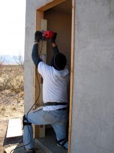
First, Brad used a template to rout out the space for the hinges, both on the frame and on the door itself.

routing

Then we did a test hang (the first of many) to check the door height and width. We needed to trim just a bit off the top and the bottom, which went smoothly.

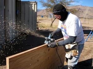
Then we worked on the width with a planer. This not only narrowed the door to fit, but also put a bevel on the door so it would close right.

planing

The process here is first to plane and then to test hang to check fit. Repeat, repeat, repeat. It took many, many times to get it just right.

Then for the last steps of several coats of varnish and installing the lock. Here is the varnished door.

I also stained and varnished the door frame, which is really looking nice. (It’s been fun to finally do something that I had some pre-existing expertise in — thanks Dad!)

You’ll have to wait to see it hung with final hardware … it’s taken me so long to get this posted that we’ve now commenced stucco’ing. And with stucco started, everything else will be on hold for a while.

Installing a Xantrex XW – part 2

Wednesday, December 30th, 2009

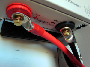
Today we mounted various components and started wiring things together. I’m afraid this will jump around a little. (And please if any one notices me doing anything suspicious, speak up.) First thing today, I connected the thick cables that will bring power from the batteries to the inverter. There is one really large breaker/disconnect between the batteries and where they connect to the inverter here. Note that I still have not connected the batteries to the system.
The heavy cables that bring power from the batteries

The heavy cables that bring power from the batteries

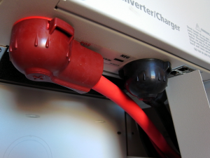
Xantrex provides covers for the power connectors

Xantrex provides nice covers for the cables

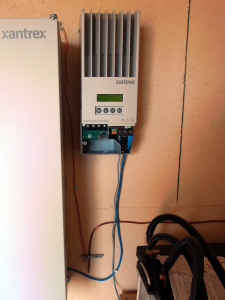
Next I mounted the other of the parts of the system: System Control Panel, Automatic Generator Start, and the Solar Charge Controller. My continuing education made a jump today when I realized why there are two battery chargers in the system. The one in the inverter converts AC from the generator, (or the grid if you have such a thing) the Solar Charge Controller converts DC from the Solar Panel array for battery charging. (It’s smarter than that actually (see MPPT), but basically that is it.)

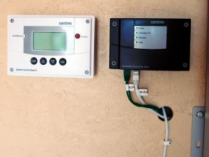
SCP and the AGS

SCP and the AGS

And, yes that is a giant heat sync built into the SCC.

Solar Charge Controller (MPPT)

Solar Charge Controller (MPPT)

You will see what look like network cables running between the different component. And, indeed they are good old CAT5 network cables. All the devices talk to each other. There’s something a little funky in the system given that each device has two network connectors and the two ends have special terminators. It seems odd to me, but I assume they are doing interesting things. (One thing that I am sure of, is that they are providing power to some of the devices.) Here’s a picture of everything mounted. The installation instructions tell you to run the network cables early because things get crowded later on. I took them at their word and ran the cables as soon as the everything was mounted.

Xantrex XW system with accesories

Xantrex XW system with accesories

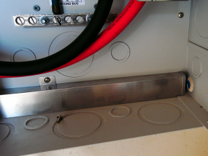
The next three pictures show the paths the network cabling take. Inside the PDP, there are special raceways for the network cabling. This is to shield the cables from interference and to help keep things organized.

From the SCC to the inverter

From the SCC to the inverter

From the inverter to SCC and the AGS

From the inverter to SCC and the AGS

SCP and the AGS

SCP and the AGS

You don’t see cabling to the SCP because it’s in the wall. For some reason, the SCP mounting hardware really wants a hole in the wall for the network cable; I obliged.

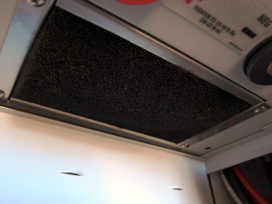
Now that I remember, the very first thing I did was install the air filter in the bottom of the inverter. You just push it in place with your hands.

The air filter

The air filter

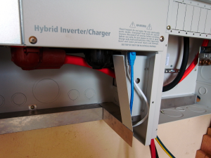
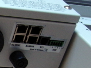
Close up of the inverter connections

Close up of the inverter connections

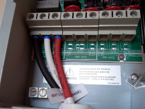
The last thing for today was to connect up the wires that bring AC from the inverter to the breakers from which the house is the next stop.

AC out from the inverter

AC out from the inverter

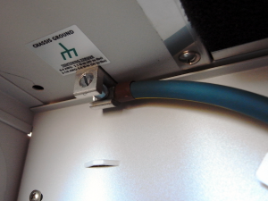
And to ground the inverter.

The ground lug in the bottom of the inverter

The ground lug in the bottom of the inverter

Installing a Xantrex XW – part 1

Tuesday, December 29th, 2009

We are completely off grid. Our Xantrex system comprises an inverter, a battery bank, and a solar array.

We got the Xantrex XW6048 inverter as the brains/workhorse of our solar-powered system. Part of the reason for going with this system (rather than pieces) is the same reason I wanted the guy doing our concrete slab also taking care of the plumbing in the slab–I don’t want any finger pointing. Also, Xantrex has a great reputation. I think everyone around here that I have visited (on my tour of places using solar power) had a Xantrex inverter and they all seemed quite happy.

I searched the web for “Installing a Xantrex XW” and found nothing – nothing useful. I hope this will help others as I seem on my own… as far as the internet goes anyway. P.D. has been enormously helpful and I’m developing a small group of great people to ask questions of via email.

Xantrex gives you really great documentation. There’s a big bound manual and a color fold-out diagram/layout that shows many possible configurations-grid tied, off-grid, single or multiple inverters, etc. It all seems a bit over my head, but I think I can work through it.

As for the rest of the system, we got the Control Panel, which lets you configure and monitor all the different parts of the system from one panel, the  Power Distribution Panel, the Solar Charge Controller, and the Automatic Generator Start. I’m sure we will need some additional parts to get it running, but was a ready to begin.

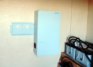
The first matter at hand is mounting the equipment. The inverter weighs something like a hundred-thirty pounds. You don’t want to fool around with this. They give you a really solid mounting plate for both the inverter and the Power Distribution Panel (hence forth know as the, PDP).

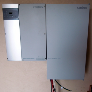
The Inverter and the PDP mounted

The Inverter and the PDP mounted

Wiring the solar panels done

Monday, December 28th, 2009

At least until I get the energy or desire to install the next six panels. We should have plenty of power for construction with six panels.

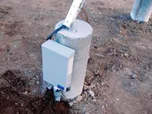
Today, we grounded the solar panels.

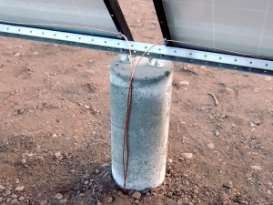
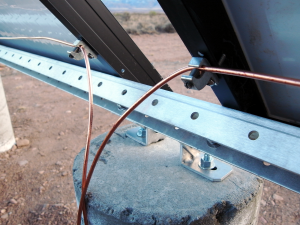
Ground wires attached

Ground wires attached

Close up of grounding lugs attached to the solar panels

Close up of grounding lugs attached to the solar panels

We also finished running the conduit from the combiner box to the battery house. Into the conduit went the hot, neutral, and ground wires from the combiner box which will hook up to the charging unit of the inverter. I also made a small change based on a recommendation from P.D.; I wrapped white tape around the two negative leads coming from the solar panels. I meant to do that just because it made clear which wires were hot and which were negative, but once they were in place, I forgot.

Wiring complete

Wiring complete

The inside cover is back on

The inside cover is back on

Buttoned up

Buttoned up

Next we’re going to work on getting the inverter up and running. The first step is mounting it. It’s a hundred and thirty pounds so it needs a solid mount. I put six 3 inch lag bolts into studs to hold it, plus quit a few sturdy screws into the OSB. It’s not going any where.

Mounting the inverter

Mounting for the inverter

Wiring the solar panels

Saturday, December 26th, 2009

The first row of solar panels is installed. It’s time to look at wiring them together.

Finished

Finished

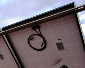
Each solar panel (data sheet, installation manual) has two cables on the back, one with a male connector and the other with a female connector. You can connect solar panels together (in series) with these cables. The more panels you connect together the greater the voltage. Because you need to have circuit breakers between the solar panels and the inverter/battery charger, you need to keep the voltages down to a level that’s reasonable for your DC breaker.

The power cables

The power cables

Our breakers can handle up to 150 volts. We will wire in groups of three panels which generates about 100 volts.

After you have connected your panels together, you’re left with one male and one female connector. One of these is positive and one is negative. These need to be connected to the combiner/breaker box. With our purchase, we got four 30 foot cables with the same connectors as the solar panels. What you do, is cut these in half (or so, depending on your arrangement) and use the two pieces to connect the solar panels to the breaker box. The end with the connector attaches to the solar panel, you strip the wire on the other end and hook it up in the combiner box. One very nice thing about this arrangement, is that you can wire the cables to the breaker box before you plug into the solar panel. This is very nice because solar panels can’t be switched off if it’s sunny.

midnight-breakerbox

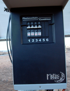
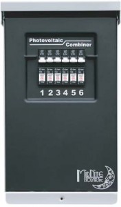
Midnite Solar MNPV6 Solar Array Combiner

The combiner box we are using is from Midnight Solar. We will use four of the available six spots for circuit breakers. If we ever find that we need to get more solar panels, all we need to do is add some breakers and we’re ready to go.

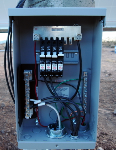
It turns out that this combiner box needs some assembly. That’s because it was designed for a variety of uses. It was pretty simple to figure out what we needed, but it was hard for me to figure out how it fit together.

There is a plate that the breakers fit into that looks like it mounts in the box; it doesn’t. It kind of hangs in the air. The breakers have a screw in the back that clamps down on the plate. Once you get a few breakers installed, it’s quite secure. This plate supplies the combined (in parallel) power of all the solar panels to the battery charger.

I have a DC lightning arrestor that will be installed in the combiner box. It connects to ground, neutral, and the combined DC output. (We actually have a variety of lightning arrestors that will go throughout the system.) I don’t really know how much protection things like this provide, but considering the lightning I’ve seen here so far, it seems worth trying.

As for grounding the panels and combiner box, I put a grounding rod into the ground (eight feet down) inside of the center back concrete column. Bare copper wire is running from the grounding rod out of the column. I’ll use this to ground all the solar panels and the combiner box. (We had to order special little connectors that attach the grounding wire to each of the solar panels.)

There was a brief hiccup before we actually wired the solar panels to the combiner box. Someone asked a question regarding the rated amps (15 amps) for for the breakers and the amps coming from the solar panels. The case is that when you connect panels in serial, the voltages add and the amps stay the same. (If you combine in parallel, the amps add and the voltage stays the same.) So, the circuit breakers we have are fine.

The wiring in pictures… Click to continue »

Let it snow!

Wednesday, December 23rd, 2009

We woke up to 3+ inches of snow this morning! And then by afternoon, most of it was gone.

Full size pics here

Wiring batteries for solar power

Wednesday, December 23rd, 2009

I am no artist.

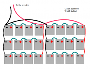
Unfortunately, the only way I could understand how to wire our batteries together was to draw a picture. Open Office has a nice drawing program. Despite its niceness, my drawing is not attractive. I think though that it’s accurate and it’s nice to have as documentation.

On a side note: Our blog is surprisingly nice for documentation. The other day I had to look up the pay load for the truck (hauling bags of cement) and it couldn’t have been easier.

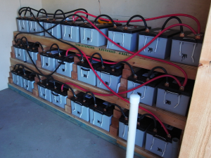
This is the physical layout as well

This is the physical layout as well

The idea here is to create one giant 48 volt battery from a bunch (24) of 12 volt batteries.

The process is to wire the batteries together both serially and in parallel. Groups of four batteries are wired together in series to get up to 48 volts. (In the picture, this is the little wires that go from positive to negative.) The blocks of 48 volts are wired together in parallel to create the giant battery. (In the picture, the red and black wires are in parallel.)

giant-battery

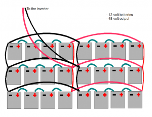
Not according to plan, but electrically correct

Yes, as Karen pointed out, not according to plan. I confess that when I bought all the solar equipment I didn’t understand exactly how it all went together. I can’t imagine what I was thinking. I didn’t have the right cables to follow my plan. I was going to order the right cables when I realized I could use what I had. Instead of linking each block together with the one above it, I link it with the one above and across. It’s the same electrically, but a little funky.

Battery details:

Sun Xtender PVX-2580L AGM Sealed Battery

Volts: 12

Amp hours: 255

This is an addendum to my original post. The battery wiring went through a little reworking. This is the final physical layout. I wouldn’t have added the horizontal wiring; however, since I had them I used them to insure the lowest possible resistance.

The final physical configuration

The final physical configuration

The wires between the batteries are 2/0 and the ones going to the inverter are 4/0.

Time permitting or time spent waiting for a lath inspection

Tuesday, December 22nd, 2009

The inspector didn’t arrive until late this afternoon. There were fewer questions by the inspector about this inspection than any one so far. We passed, and it’s on to stuccoing. Once, that is, the threat of rain (and snow) has passed.

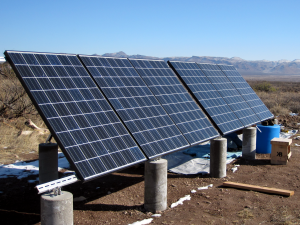
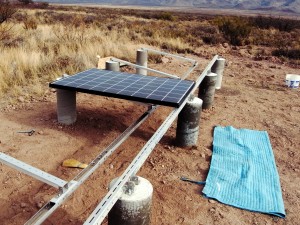
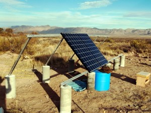
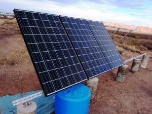
While I was waiting, I buckled down and got to work on the solar panel mounting. I got four of the first six panels up before it got dark.

The front edge bolted down

The front edge bolted down

The first of the back edge posts attached

The first of the back edge posts attached

Close up

Close up

Making progress on the back edge

Making progress on the back edge

The back edge is ready for the solar panels

The back edge is ready for the solar panels

Positioning the first panel on the front edge

Positioning the first panel on the front edge

Two panels up

Two panels up

Three panels up

Three panels up

Four panels up

Four panels up

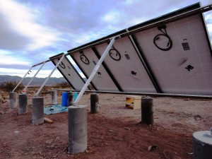
A picture of thebackside

A picture of thebackside

I don’t really love the mounting hardware, but I’m not sure how I’d do it differently. It relies completely on the solar panel itself for lateral strength. I wonder if some kind of X bracing is in order.

Thanks for the help with this Douglas!

We passed!

Monday, December 21st, 2009

Time permitting…

Sunday, December 20th, 2009

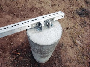
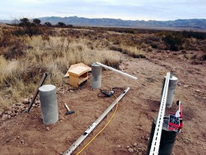
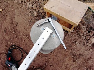
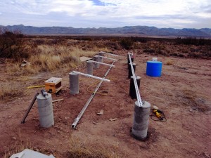
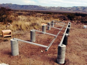
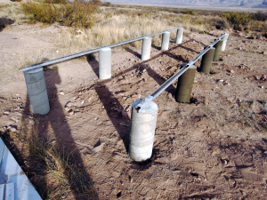
We will get the first solar array up and running. The columns are poured and ready to go.

Our focus will remain on stucco for Tumbleweed; however, spare moments will likely go into solar power.

columns-finished