I know we haven’t written much lately, but we are still here, moving ahead.
It is the time of year when I am doing a fair amount of travel for work (CA, TX, CA again, WA, etc.), which also means I have a lot of work to be doing in the office getting ready for various conferences, meetings, and workshops. (I am duping and printing CDs as I write this.) I have not been working much on the house the last couple weeks. As a result, I am a bit sullen and cranky, but it is good at least to be bringing in some money.
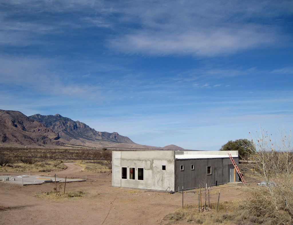
Brad has been working on electrical, pulling wires and putting in outlets and switches. He is finding it to be a bit tedious and not quite as gratifying as, say, stucco’ing, but it must be done. Next will be plumbing. Then some more really fun stuff…dry wall, paint, plaster, and tongue and groove plank ceilings.
We also have one other new project in our lives (because we have so much free time on our hands :). We are doing some work with a small local farm here.
My interest in this started when I read the book Hope’s Edge: The Next Diet for a Small Planet by Frances Moore Lappe. It is a remarkable book about the dissonance between the world most of us want to live in and the lives we actually live. The truth is that most of the decisions we make in our lives don’t support a sustainable clean planet and a just society for all of its people. The book goes way beyond sustainable food choices to deal with social issues like land reform, world hunger, economics, labor markets, and much more. Lappe’s overarching theme is that the small choices we make in our everyday lives affect all these parts of our society. The book is also part travel journal with the storyline following Lappe’s journey around the world with her daughter to look at these issues by talking with a variety of interesting people.
Anyway, some of the discussions in the book about things like organic growing, small farms, sustainable food choices, and community involvement made me think more about the small local farm here that we bought produce from last year. At the end of the last growing season, we had heard the couple from this farm say that they were having some challenges. The more I thought about it, the more I wanted to get involved somehow. And while I know nothing about farming, I am a good marketer and small business person, so after much deliberation, I asked them if we might lend a hand.
Their response was amazing: YES! “We are thrilled for community involvement at any level individuals are willing to contribute. Our hopes are that our community would consider this their own local farm and would invest in it and help it prosper.”
Since then we’ve met several times and are hard at work on moving ahead with things. It’s loads of fun and like other things here, it is making us look at the world in some new ways.